IGCC process heat transfer
통합 가스화 복합 사이클 설비에서 열 전달 공정을 최적화하는 것은 어려운 일입니다. 가스화, 가스 이동 및 가스 세정 공정에 대한 특정 요구 사항을 충족시키기 위해 알파라발은 비용과 환경 영향을 줄이면서 신뢰성, 에너지 효율 및 출력을 향상시키는 광범위한 전문 지식, 장비 및 서비스 포트폴리오를 제공합니다.
Optimizing IGCC heat transfer processes
IGCC 플랜트 출력을 늘리려면 비용과 환경 영향을 줄이는 신뢰할 수 있고 에너지 효율적인 열 전달 솔루션이 필요합니다. 가스화, 가스시프팅 및 가스 클리닝 아일랜드 사이에서 IGCC 설비는 각각 특정 요구 사항이 있는 다수의 공정 열교환기를 필요로 합니다. 작동온도 및 압력, 재질, 파울링, 청소 서비스, 사이클링 또는 꾸준한 작동 여부와 상관없이 솔루션은 매우 안정적이어야 합니다. 알파라발의 포트폴리오는 대부분의 요구 사항에 적합한 솔루션을 제공합니다.
알파라발 전문가는 쉘 앤 튜브 열교환기, 용접 플레이트 열교환기 및 개스킷 플레이트 열교환기를 주어진 응용 분야에 필요한 기계적 강도, 내식성, 공정 성능 및 원하는 작동 기능의 조합에 충족시킬 수 있습니다.
Alfa Laval Olmi 쉘-튜브 열교환기는 간단하고 견고한 디자인과 특수 합금 구조로 극한 공정 조건을 견딜 수 있습니다. 최대 450 bar의 압력 및 1000 ° C (1863 ° F) 이상의 온도에서 안정적인 작동을 제공합니다.
알파라발 용접 판형 열교환기는 원유 및 역청에서 아스팔트, 슬러리 오일 및 슬러지에 이르기까지 광범위한 매체를 포함하는 광범위한 공정을 위한 작고 효율적인 열 전달의 또 다른 예입니다.
경쟁력을 유지하기 위해 IGCC 플랜트 소유자와 운영자는 알파라발을 사용하여 가장 까다로운 IGCC 프로세스에 큰 가치를 제공합니다.
Alfa Laval Packinox installations
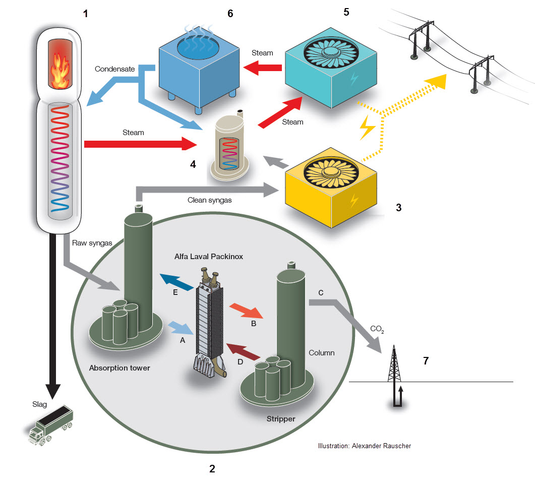
Process overview

1. Gasifier
The coal is gasified into a synthesis gas, the “left over” (slag) is taken away for disposal. The syngas is cooled down and transferred to the gas cleaning part of the process.
2. Gas cleaning
The cool raw syngas is introduced at the bottom of the absorption tower, where it makes contact with a solvent (selexol) that travels downwards through the tower’s packing material. CO2 is absorbed by the solvent. Rest of the gas (now cleaned) goes out through the chimney.
A. Cold solvent with the CO2 goes through the Alfa Laval Packinox heat exchanger and is heated up on its way to the stripper tower.
B. Warm solvent with CO2 goes into the top of the stripper tower and then travels downwards. Steam is introduced at the bottom of the tower and travels upwards, encountering the solvent. The heat of the steam releases the CO2.
C. A mix of steam and CO2 leaves the top of the stripper. It is later cooled down to water and CO2, where the CO2 is compressed prior to storage / injection into old oil wells.
D. The clean solvent goes back in a closed loop to the absorption tower. On its way back to the absorption tower the hot clean solvent passes through the heat exchanger and is thereby heating up the solvent (with CO2) that is on its way to the stripper tower.
E. When the clean solvent heats up the cold solvent (with CO2) it is thereby cooled down. Back in the absorption tower the clean cold solvent is used to capture more CO2.
3. Gas turbine
The clean syngas is combusted in the gas turbine to generate electricity.
4. Boiler
The flue gas from the combustion is transferred to the boiler where it is heating water to generate steam.
5. Steam turbine
The steam generates additional electricity – the majority of the electricity in the IGCC plant is generated by the steam turbine.
6. Condenser
The condenser then cools down (condenses) the steam to water which is reused for cooling the raw syngas in step one of the process. The raw syngas heats up (while cooling down) the condensate which turns into steam that goes back into the boiler for further electricity generation.
7. CO2 storage
The captured and compressed CO2 is injected into old oil wells under high pressure, thereby pushing up additional oil from the well. The CO2 remains – and is thereby stored – in the geological formation.

